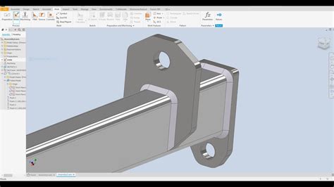
weld sheet metal inventor The welding capabilities within Inventor are currently limited to parts within a weldment assembly - that is, you can not simply create a physical weld within a part (or sheet metal part). The “Basic Theory of Driving” handbook is essential reading for all road users in Singapore, which comprise the pedestrians, cyclists, motorcyclists and drivers. It covers The Highway Code, which includes the traffic rules, traffic regulations, traffic signs and signals, and it aims to educate and promote road safety for the road users.
0 · inventor 2023 Tutorial Steel welding Modeling
1 · Solved: Spot Welds
2 · Sheetmetal Welding
3 · Sheet Metal Weld
4 · MFG323109 20+ Tips for Creating Weldments in Autodesk
5 · Inventor, can I convert a standard iam assembly to an
6 · Inventor 2023 Help
7 · Inventor 2022 Help
8 · Inventor
9 · How to Weld a part
10 · 2
Order metallic quilting fabric online at Fat Quarter Shop. Our premium metallic fabric by the yard is sure to add attractive sheen, sparkle, and shine to your next project. With free shipping for orders over $80, buy your metallic print fabric .
The welding capabilities within Inventor are currently limited to parts within a weldment assembly - that is, you can not simply create a physical weld within a part (or sheet metal part).One trick that I have used with imported sheet metal parts (Hoffman enclosures, .Learn when and how to use weld features or cosmetic welds to help with assembly .I have found that if you intend to create something like a "tank" to hold fluids, .
The new Laser Weld corner relief terminates with a tangent arc and is .I see sheet metal prints where the proper symbol will be used at the location, then .
Solution: Yes you can weld sheet metal parts but they must be in a weldment . One trick that I have used with imported sheet metal parts (Hoffman enclosures, for example) is to Delete Face w/Heal all the adjacent faces, giving a sharp corner, then apply the appropriate fillets for an impossibly perfectly .Learn when and how to use weld features or cosmetic welds to help with assembly size and performance, drawing automation, and specialized weld state drawing views. About the . I have found that if you intend to create something like a "tank" to hold fluids, Inventor works quite well, providing you aren't trying to do it inside of the sheet metal .
Familiarize yourself with these different weld types and their applications. Inventor supports various welding types, including fillet welds, groove welds, spot welds, and more. Inventor - Weld corner example This video is part of a series that was created for the Handout for the Autodesk University class: 323109 Getting you Welders and Designers Connected (20 Tip.The new Laser Weld corner relief terminates with a tangent arc and is more suitable for laser cut parts. For more information about corner reliefs, see To Work with Corners in Sheet Metal .
I see sheet metal prints where the proper symbol will be used at the location, then have an X located at preferred locations for the actual welds. Chris
inventor 2023 Tutorial Steel welding Modeling

Solved: Spot Welds
Solution: Yes you can weld sheet metal parts but they must be in a weldment assembly, see below on how to convert a standard assembly to a weldment assembly. You mistakenly start and created a standard Inventor iam . Inventor Forum > Creating Fill Weld in the Corner of two bends in a sheet metal part; Options. Subscribe to RSS Feed; . Creating Fill Weld in the Corner of two bends in a sheet metal part Anonymous. Not applicable 01-13-2006 12:28 PM. Mark as New; Bookmark; Subscribe; . groove weld is the right one to start with as fillet welds don't .

About Press Copyright Contact us Creators Advertise Developers Terms Privacy Policy & Safety How YouTube works Test new features NFL Sunday Ticket Press Copyright .
I haven't done anything for welding in inventor. Forums Home > Inventor Community > Inventor Forum > Spot Welds; Inventor. Community Forums; Inventor Forum . I see sheet metal prints where the proper symbol will be used at the location, then have an X located at preferred locations for the actual welds. Chris. Report. 0 Likes Overlapping Flange for Seam Weld in Sheet Metal I'm trying to create an overlapping flange from two adjacet previosly created flanges. . There is a workflow allowing this case to work in Inventor. But, it could be risky. Here is what you need to do. Move EOP to right under Flange3. Create a zero-offset workplane on the outer face of Flange3 . In our software (SigmaNEST), we are able to create a sketch on the Inventor part file (if sheet metal, the sketch has to be in the Flat Pattern), and give it a particular name. Then in the nesting software, we set it to look for that sketch name for the Marking process, similar to how layers would be used in an AutoCAD-based pattern.
Could anyone help please, I'm using Inventor 2008 Pro in the sheet metal format, and having a slight problem with corners!! . Change to Linear weld, and gap to 0.1mm. This should automatically set your corners 0.1mm without doing corner seam, since physical bending will not easily achieve a 100% angle precision, 0.1mm is acceptable. .Welding aluminum is not hard at all, and extremely common. Braking aluminum presents different design criteria but again, not at all uncommon. There are alloys better for it as opposed to casting, machining, or extruding, of course. Some time at a metal fab job shop and I saw a lot of aluminum work come through, and had to do a lot of welding, too. Start a new "weldment".. place your sheet metal part into it and do a fillet and cosmetic weld to fill in the gaps.. Something like this.. Inventor 2023 - Dell Precision 5570
The corner seam will not work on the contoured edge nor will any other sheet metal function such as bend or flange on the edge as seem in the picture. Im not sure why this is such a simple part youd think it would be so easy haha. Even if i solid model it and convert to . Inventor supports various welding types, including fillet welds, groove welds, spot welds, and more. Familiarize yourself with these different weld types and. A groove weld doesn't quite work, a fillet weld doesn't either. In reality, the weld is smooth and consistent across the gap, with no holes in the corner, Inventor could add in a feature wthin the weld environment to recognise this and modify the weld to seal the entire gap of the sheet metal, what I an terming "Weld to seal".
If so, it is good practice to create a sheet metal style and not just uncheck use thickness from rule and alter the thickness. Instead use the pencil icon and create sheet metal default for your company thickness. That way you have a dedicated style for each thickness of material and can control relief shapes and bend rads per thickness. I just started working with sheet metal in Inventor (2020) and am currently modeling the baseplate of my circular saw as I intend to design a dust collection shroud for it. I've been able to model the part with a sketch; I formed a face and changed the gauge of the metal. So far so good. I went to bend up the edges with the flange tool and it seems I cannot flange . Hi, I have created a sheet metal box enclosure (Inventor 2008) but am really struggling to weld the seams up? When the model is in its folded state there is a gap running up each corner. I have tried converting to a weldment, using the weld tool etc. (all wrong obviously). Could anyone point me in the right direction please? Hi forum members, new to inventor (less than a month of using) I seem to have challenges when using sheet metal especially when it comes to welding. It's always a hit or miss. In this case, this particular folded sheet .
Hi. I am messing around with a part at the moment so if I was to put it up as an .ipt file it would be crucified for not being constrained, dimensioned etc etc. I am stumped I have to say. I am trying to get a 25 and 20mm return fold .
Can somebody take a look at the picture attached and tell me whats the best way to make tabs on a rolled round ring. I got it done using unfold/refold option but I can not get sheet metal flat. Let me know if there is a good method . I am having a problem with sheet metal corners after adding corner seam with overlap. I am using the same sheet metal settings for the corner seam command that I am using my flanges. When I add the corner seam with my standard GapSize (.001") with a relief shape of Arc Weld or Linear Weld, the corner relief corner changes to what you see in the second photo. Try and keep all your sheet metal sketches on the same plane. Sketch 1 was on the XY plane - make Sketch2 on the XY plane as well. Keep it simple. Test frequently. If you repeat the above steps, when you draw the circle, place a "Point" at the center of the circle. Create the cut feature. Extract the Cut feature as a sheet metal punch iFeature. The only way I found to make it look "right" is to choose Arc Weld for the corner relief shape. Sam B Inventor 2012 Certified Professional Please click "Accept as Solution" if this response answers your question.-----Inventor Professional 2013 SP1.1 Update 1 Windows XP Pro 32-bit, SP3 HP EliteBook 8730w; 4 GB RAM; Core™ 2 Duo T9400 2.53 GHz .
Setelah mendaftar dan menyelesaikan kursus ini kamu akan menguasai 4 materi utama antara lain : 1. 3D Sheet Metal Modeling 2. 3D Frame & Chasis Modeling 3. 3D Welding Modeling 4. 2D Drawing Sheet Metal, Frame & Welding Hello, again. I'm sorry to be a burden to the community but I have yet another problem. When making things out of sheet metal I want to add a series of tabs to the outer edges so that they can be assembled and riveted together and I can bottom how to do it without a lot of work. So basically if I have a square like this I can extrude it or thicken it in the normal way but .

Welcome to Autodesk’s Inventor Forums. Share your knowledge, ask questions, and explore popular Inventor topics. . Those corners styles are set in the sheet metal rules. As for welding, as far as I know, you'll need to insert the sheetmetal part into a weldment assembly. Preview file 124 KB Report. 1 Like Reply. In this video Pete will demonstrate a technique for creating an elliptical sheet metal flange, when the Contour Flange tool is unable to do so. This will al.
Welcome to Autodesk’s Inventor Forums. Share your knowledge, ask questions, and explore popular Inventor topics. All community This category This board Knowledge base Users Products cancel Sheet metal and welding go hand in hand, Autodesk Inventor has some really sweet tools to make short work out of these designs. However Inventor occasionally tends to disagree. I use the case of this weekend, where I was simply wanting to see how a part was going to pan out in the grand scheme of things. Attached is an image of what I am trying to accomplish. I took what I knew of the sheet metal and applied it to a standard 3d model to see if i could convert and flat pattern. But inventor wasn't having any of my shenanigans. I would like to be able to basically stamp or die cut a pattern into the sheet steel. Then fold the steel outer section one way and the inner section .
Sheetmetal Welding

metal enclosure modification
Unlock endless creativity with the first machine that combines laser, inkjet blade cutting and even printing, turning ideas into reality effortlessly. The best budget-friendly diode laser machines for home-use and DIY users - include 5W and .
weld sheet metal inventor|Inventor